ArduPilot LTE Network Setup With Serial Interface
Video Tutorial
This tutorial covers setting up LTE-based MAVLink telemetry for ArduPilot using the Vimdrones Telemetry LTE Base Board with a SIM7600 PCIE module.
ArduPilot's LTE support is implemented as a Lua scripting driver (LTE_modem.lua), written by >Andrew Tridgell. The driver manages the modem entirely via AT commands — no manual AT command configuration is needed. Two connection modes are available:
- TCP Mode (
LTE_PROTOCOL=2) — MAVLink2 over a direct TCP connection to a server. - PPP Mode (
LTE_PROTOCOL=48) — Full IP link via PPP, requires custom firmware with PPP support.
Hardware Required
- Vimdrones Telemetry LTE Base Board
- SIM7600 PCIE module (any SIM7600 variant, e.g. SIM7600G-H, SIM7600E-H)
- Nano SIM card with active LTE data plan
- Flight controller with ArduPilot and a microSD card (e.g. Pixhawk 6X, Cube Orange)
- A server with a publicly accessible IP address running a TCP/UDP proxy program (see note below)
Software Required
- LTE_modem.lua scripting driver
- GCS: MAVProxy | QGroundControl | Mission Planner
- (PPP mode only) Custom firmware with PPP support — build at custom.ardupilot.org
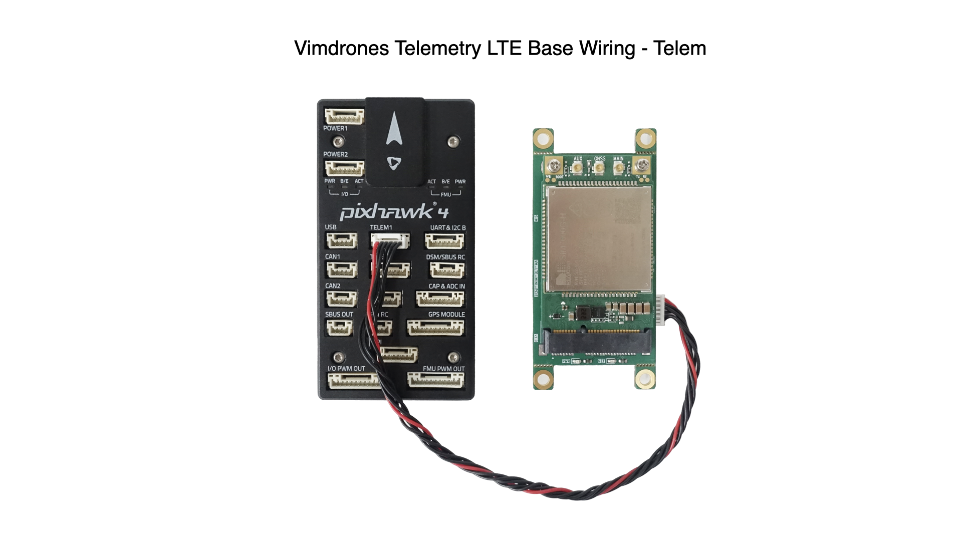
Wiring
Connect the LTE Base Board to the flight controller Telem port:
Hardware Flow Control for Higher Baud Rates
When using baud rates above 115200 (e.g. 921600), enable hardware flow control (RTS/CTS) on the serial port by setting BRD_SERn_RTSCTS 1 for the port connected to the LTE board. Without flow control, data loss may occur at higher speeds.
Power
The board can be powered from the Telem port 5V rail or from a 2S–6S battery via the XT30 connector. Use the XT30 when drawing more current — the SIM7600 can peak at ~2A during transmission.
Step 1 — Install the Lua Script
Download LTE_modem.lua and copy it to the APM/SCRIPTS/ directory on the flight controller's microSD card (via direct access or MAVFTP).
Step 2 — Initial ArduPilot Parameters
Enable scripting and set the serial port connected to the LTE board to Scripting mode. This example uses SERIAL2 (Telem2):
SCR_ENABLE          1       # Enable Lua scripting
SCR_SDEV_EN         1       # Enable scripting serial devices
SERIAL2_PROTOCOL    28      # Set serial port to Scripting
Reboot the flight controller and refresh parameters — the LTE_* parameters will now appear.
Option 1: TCP Mode (MAVLink2 over TCP)
This mode connects the modem directly to a TCP server and sends MAVLink2 data. No PPP or custom firmware required.
Parameters
Replace the IP address with your server's address (shown as 157.245.83.174 below as an example using the ArduPilot support server):
SCR_SDEV1_PROTO     2       # MAVLink2 on scripting serial device 1
LTE_ENABLE          1
LTE_PROTOCOL        2       # TCP / MAVLink2 mode
LTE_SERPORT         2       # Matches SERIAL2
LTE_SCRPORT         1       # Scripting serial device index
LTE_SERVER_IP0      157     # Server IP octet 1
LTE_SERVER_IP1      245     # Server IP octet 2
LTE_SERVER_IP2      83      # Server IP octet 3
LTE_SERVER_IP3      174     # Server IP octet 4
LTE_SERVER_PORT     20001   # Server TCP port
LTE_BAUD            115200  # Baud rate to modem
GCS Server
A server-side program is required
The LTE modem connects outbound from the drone to a server — your GCS cannot connect directly to the drone. You must run a TCP/UDP server program on a machine with a public IP address that your GCS then connects to.
Options:
- ArduPilot Support Server — hosted, no setup required
- UDPProxy — self-hosted MAVLink proxy (recommended for self-hosting)
- Any TCP/UDP relay or tunnel program that forwards the connection to your GCS
# MAVProxy example — connect to the server TCP port
mavproxy.py --master=tcp:<SERVER_IP>:20001
Option 2: PPP Mode
PPP mode provides a full IP link from ArduPilot over LTE. This enables ArduPilot networking features (NET_* parameters) and requires custom firmware with PPP compiled in.
Build Custom Firmware
Go to custom.ardupilot.org, enable the PPP feature, and download the firmware for your flight controller.
Parameters
SCR_SDEV1_PROTO     48      # PPP on scripting serial device 1
LTE_ENABLE          1
LTE_PROTOCOL        48      # PPP mode
LTE_SERPORT         2       # Matches SERIAL2
LTE_SCRPORT         1       # Scripting serial device index
LTE_BAUD            115200  # Baud rate to modem
NET_ENABLE          1       # Enable ArduPilot networking
NET_P1_TYPE         3       # TCP client
NET_P1_IP0          157     # GCS server IP octet 1
NET_P1_IP1          245     # GCS server IP octet 2
NET_P1_IP2          83      # GCS server IP octet 3
NET_P1_IP3          174     # GCS server IP octet 4
NET_P1_PORT         20001   # GCS server TCP port
GCS Server
A server-side program is required
Same as TCP mode — ArduPilot connects outbound to the server IP set in NET_P1_*. You need a TCP/UDP server program with a public IP address. Options: ArduPilot Support Server, UDPProxy, or any compatible TCP/UDP relay.
Once PPP is connected, ArduPilot will establish a TCP connection to the configured NET_P1_* address. Use MAVProxy or Mission Planner to connect to the server.
Status Messages
The driver reports connection state via GCS messages:
| Message | Meaning |
|---|---|
LTE_modem: starting |
Driver initialising |
LTE_modem: found modem |
Modem detected and responding |
LTE_modem: CREG OK |
Network registration successful |
LTE_modem: connected |
TCP/PPP connection established |
LTE_modem: connection closed, reconnecting |
Connection lost, retrying |
LTE_modem: timeout |
No data within timeout period |
Troubleshooting
| Symptom | Check |
|---|---|
LTE_* params not appearing |
Confirm SCR_ENABLE 1, script is in APM/SCRIPTS/, reboot and refresh params |
| No LTE registration | Verify SIM card inserted (Nano SIM), cellular antenna connected, SIM has data plan |
| No UART data | Check TX/RX wiring and confirm the correct LTE_SERPORT index |
| Power drops / resets | SIM7600 peaks ~2A — power via XT30, not Telem 5V |
| PPP not connecting | Ensure PPP is compiled into firmware (custom.ardupilot.org) and NET_ENABLE 1 |
| Need roaming | Send AT+CREG=2 and AT+CGREG=2 to the modem via USB terminal |
Debug Log
The driver writes all AT command communication to LTE_modem.log on the SD card. Check this file first when troubleshooting.